



Important
GPIO Limitation: AtomS3 provides very few GPIOs. This solution works best for:
- Supervising multiple RS485 BMS
- Limited number of UART BMS (3 maximum)
- Applications where compact size is priority
The M5Stack AtomS3 combined with the Atomic CAN Base provides a compact and powerful solution for YamBMS applications. This combination offers CAN bus communication with isolation, a built-in display, and expandability through additional M5Stack units.
Key Features:
- Compact design (24×24×13mm AtomS3 footprint)
- ESP32-S3 with 8MB Flash
- Built-in 0.85" IPS display (128×128 pixels)
- Isolated CAN bus communication (up to 1Mbps)
- 6-axis IMU (MPU6886)
- Expandable with M5Stack Units (RS485, CAN, etc.)
- Programmable button
- Multiple development platforms supported
Choose one AtomS3 controller to clip onto the Atomic CAN Base:
| AtomS3 Lite | AtomS3 | AtomS3R (8MB PSRAM) |
|---|---|---|
 |
 |
 |
| Model | Flash | PSRAM | Display | IMU | Best For |
|---|---|---|---|---|---|
| AtomS3 Lite (C124) | 8MB | No | 0.85" IPS | MPU6886 | Budget projects |
| AtomS3 (C123) | 8MB | No | 0.85" IPS | MPU6886 | Standard applications |
| AtomS3R (C126) | 8MB | 8MB | 0.85" IPS | MPU6886 | Recommended (extra RAM) |
Recommendation: Choose AtomS3R (C126) if using Bluetooth BLE for BMS communication, as the extra 8MB PSRAM helps prevent crashes when the BLE stack consumes significant RAM.
| Atomic CAN Base | CAN Unit | RS485 Unit |
|---|---|---|
 |
 |
 |
| Component | Type | Features | Use Case |
|---|---|---|---|
| Atomic CAN Base (A103) | CAN Base | Isolated CAN, up to 1Mbps, 110 nodes | Recommended for inverter |
| CAN Unit (U085) | HY2.0 Unit | Isolated CAN via Grove port | Alternative CAN solution |
| RS485-ISO Unit (U094) | HY2.0 Unit | Isolated RS485, up to 500kbps, 256 nodes | For RS485 BMS or multi-node |
Based on hardware limitations and testing, this board supports:
| Interface | Maximum | Notes |
|---|---|---|
| CAN | 1x bus | CAN bus to BMS or Inverter (after adding a CAN base/unit) |
| RS485 | 1x bus | Best option for monitoring many BMS of the same brand (after adding a RS485 base/unit) |
| UART | 3× devices¹ | CAN be connected to the HY2.0 interface or Atomic Base GPIOs header (shared with RS485) |
| Bluetooth (BLE) | 3× devices¹ | BLE stack consumes significant RAM, may cause crashes/reboots |
¹ BMS / Balancer / Shunt
Note: These are theoretical limits. Not all combinations have been tested. For large installations with many BMS units, consider boards with more GPIOs like the LilyGo T-Connect or Waveshare ESP32-S3-RS485-CAN.
| Specification | Details |
|---|---|
| Microcontroller | ESP32-S3FN8 |
| Processor | Xtensa 32-bit LX7 dual-core @ up to 240MHz |
| Flash | 8MB |
| PSRAM | None (AtomS3 Lite/AtomS3) / 8MB Octal SPI (AtomS3R) |
| Display | 0.85" IPS LCD, 128×128 resolution |
| UART | 1x HY2.0 interface (not isolated) |
| IMU | MPU6886 (6-axis gyro + accel, I2C 0x68) |
| Button | 1× Programmable button |
| Infrared | IR transmitter built-in |
| USB | USB Type-C (power + programming) |
| DC-DC | SY8089 (5V to 3.3V) |
| Power Input | 5V via USB Type-C |
| Operating Temp | 0°C ~ 40°C |
| Dimensions | 24.0 × 24.0 × 12.9mm |
| Weight | 6.9g |
Available GPIOs (Bottom Pins):
- G5 / G6 / G7 / G8 / G38 / G39
- Power: 5V, 3.3V, GND
HY2.0-4P Expansion Port:
| Pin | Color | Function |
|---|---|---|
| 1 | Black | GND |
| 2 | Red | 5V |
| 3 | Yellow | G2 |
| 4 | White | G1 |
Internal Connections:
| Peripheral | GPIO Pins | Notes |
|---|---|---|
| LCD Display | MOSI: G21, SCK: G17, CS: G15, RS: G33, RST: G34, BL: G16 | SPI interface |
| MPU6886 (IMU) | SDA: G38, SCL: G39 | I2C address 0x68 |
| IR Transmitter | Built-in | For infrared control |
| Specification | Details |
|---|---|
| CAN Transceiver | CA-IS3050G (isolated) |
| Maximum Rate | 1 Mbps |
| Supported Nodes | Up to 110 nodes |
| Loop Delay | 150ns (low) |
| Common-mode Voltage | -12V to +12V |
| Isolation | Built-in isolated DC-DC |
| Protection | Signal protection + electrical line protection |
| External Port | VH3.96-4P terminal block |
| Operating Temp | 0°C ~ 40°C |
| Dimensions | 24 × 48 × 18mm |
| Weight | 11.1g |
The Atomic CAN Base connects to AtomS3 through the bottom pins:
| Pin | LEFT | RIGHT | Pin |
|---|---|---|---|
| 1 | 3.3V | ||
| 2 | 3 | UART_TX (CAN_TX) | |
| 4 | 5 | UART_RX (CAN_RX) | |
| 5V | 6 | 7 | |
| GND | 8 | 9 |
CAN Terminal Block (VH3.96-4P):
- CAN H (CAN High)
- CAN L (CAN Low)
- GND (Ground)
Note: The exact UART pins used depend on configuration. Check the schematic for GPIO assignment.
If you need RS485 communication (e.g., for RS485 BMS, multi-node), add the RS485-ISO Unit (U094):
| Specification | Details |
|---|---|
| Isolation Chip | CA-IS3082W |
| Maximum Rate | 500 kbps |
| Supported Nodes | Up to 256 nodes |
| Isolation Voltage | 1000V RMS |
| Protection | Fail-safe, Overcurrent, Thermal shutdown, ±15kV ESD |
| Connection | HY2.0-4P Grove cable to AtomS3 |
| Terminal | VH-3.96 4P (A, B, GND, +V) |
| Dimensions | 56.0 × 24.0 × 10.2mm |
| Weight | 9.1g |
RS485-ISO Unit Pinout:
| HY2.0-4P | Black | Red | Yellow | White |
|---|---|---|---|---|
| PORT.C | GND | 5V | UART_RX | UART_TX |
Termination Resistor: The RS485-ISO Unit includes a 120Ω termination resistor (provided separately) that can be connected when the unit is at an endpoint of the RS485 bus.
The Atomic CAN Base provides isolated CAN communication via a VH3.96-4P terminal block.
| CAN bus | Terminal Block (VH3.96-4P) |
|---|---|
| CAN H | H (CAN High) |
| CAN L | L (CAN Low) |
| GND | GND (optional) |
Wiring Steps:
- Clip the AtomS3 onto the Atomic CAN Base (ensure proper alignment)
- Identify CAN H and CAN L wires from your inverter or CAN device
- Connect CAN H to H (CAN H terminal)
- Connect CAN L to L (CAN L terminal)
- Connect GND to GND for common reference (optional)
CAN Bus Best Practices:
- The Atomic CAN Base features built-in isolation for protection
- CAN bus operates at up to 1 Mbps data rate
- Supports up to 110 nodes on the bus
- Use twisted pair cable (120Ω impedance recommended)
- Termination: Add 120Ω resistors at both ends of the CAN bus
- If the AtomS3 is at an endpoint, connect a termination resistor
- Check if your inverter has built-in termination before adding external resistors
If using the RS485-ISO Unit for RS485 devices:
| RS485 | Terminal Block (VH3.96-4P) |
|---|---|
| A + | A (Data+ non-inverting) |
| B - | B (Data- inverting) |
| GND | GND (Ground reference) |
Wiring Steps:
- Connect the RS485-ISO Unit to the AtomS3 via the HY2.0-4P Grove cable (Yellow=RX, White=TX)
- Identify A and B wires from your RS485 device (often labeled D+/D- or A/B)
- Connect RS485 A (D+) to Pin 1 (A terminal)
- Connect RS485 B (D-) to Pin 2 (B terminal)
- Connect GND to Pin 3 for common reference (recommended)
RS485 Best Practices:
- The RS485-ISO Unit features 1000V isolation for protection
- RS485 operates at up to 500 kbps data rate
- Supports up to 256 nodes on the bus
- Use twisted pair cable for noise immunity
- Termination: Connect the included 120Ω resistor between A and B if the unit is at an endpoint
- The unit includes fail-safe protection (outputs high if input is open or shorted)
USB Type-C Power:
- Connect a USB Type-C cable for 5V power
- Recommended for programming, debugging, and testing
- Built-in SY8089 DC-DC converter steps down 5V to 3.3V for ESP32-S3
- Typical power consumption: 150-300mA (idle to active WiFi)
External 5V via HY2.0-4P Grove port:
- Useful when powering the entire assembly from an external 5V supply
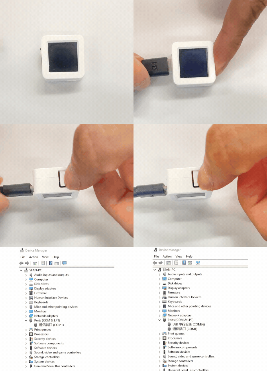
If you have trouble uploading firmware to the AtomS3:
Manual Download Mode:
- Press and hold the RESET button (about 2 seconds)
- Wait until the internal green LED lights up
- Release the button
- The device is now in download mode and ready for flashing
Important: The PWM signal frequency for the LCD backlight driver should be 500Hz. A frequency that is too high may cause abnormal brightness adjustment functionality.
Backlight GPIO: G16
| Specification | Details |
|---|---|
| Size | 0.85 inch IPS LCD |
| Resolution | 128 × 128 pixels |
| Color Depth | 65K colors |
| Driver IC | GC9107 |
| Interface | SPI |
| Backlight | PWM controlled (GPIO16) |
The AtomS3's display can be controlled with the following parameters (useful for YamBMS display management):
Backlight Settings:
- Backlight control: Manual brightness control (0-100%)
- Backlight max level: Limit the maximum brightness in general
- Backlight auto-dim level: Desired brightness when dimmed down (set to 0 to switch off screen completely)
- Backlight auto-dim time: Time in minutes after which the screen will dim down (set to 0 to disable auto-dimming)
Behavior Notes:
- Device restores last screen brightness after boot
- Auto-dim timer does not start automatically - it gets initially started by pressing the screen button
- Button press bumps brightness to 100% until the timer dims down again
- This provides a lightweight solution without complex automation
The AtomS3 includes a built-in MPU6886 6-axis IMU:
| Sensor | Details |
|---|---|
| Model | MPU6886 |
| Interface | I2C (address 0x68) |
| Pins | SDA: GPIO38, SCL: GPIO39 |
| Features | 3-axis gyroscope + 3-axis accelerometer |
Use Cases for YamBMS:
- Orientation detection
- Vibration monitoring
- Installation angle verification
- Advanced motion-based alerts (optional)
Note: The I2C pins on the back of the AtomS3 share the same bus with the MPU6886.
Best for: Multiple RS485 BMS + inverter via CAN
Components:
- AtomS3R (recommended)
- Atomic CAN Base (A103)
- RS485-ISO Unit (U094)
Connections:
- Clip AtomS3R onto Atomic CAN Base
- Connect inverter to CAN terminal (CAN H/L)
- Connect RS485-ISO Unit to AtomS3 via Grove cable (HY2.0-4P)
- Connect BMS RS485 bus to RS485 terminals (A/B)
- Power via USB Type-C
- Add termination resistors at bus endpoints
GPIO Usage:
- CAN: Uses UART pins via Atomic CAN Base
- RS485: Uses G1/G2 via HY2.0-4P Grove port
- Display: Internal SPI (pre-configured)
Best for: 2-3 BLE devices + inverter via CAN
Components:
- AtomS3R (8MB PSRAM required for stable BLE)
- Atomic CAN Base (A103)
Connections:
- Clip AtomS3R onto Atomic CAN Base
- Connect inverter to CAN terminal
- Configure BMS via Bluetooth (up to 3× BMS maximum)
- Power via USB Type-C
Limitations:
- BLE stack consumes significant RAM
- May cause crashes/reboots with >2 BMS
- No physical RS485 connection
- Solution: Press and hold RESET button (~2 seconds) until green LED lights up, then release
- Try different USB cable (must support data transfer)
- Check USB drivers are installed
- Verify CAN H and CAN L are correctly connected (not swapped)
- Check that CAN bus has exactly two 120Ω termination resistors (one at each end)
- Verify CAN bus speed matches inverter (typically 500kbps)
- Measure resistance between CAN H and CAN L (should be ~60Ω with proper termination)
- Check isolation: the Atomic CAN Base has built-in isolation, but verify connections
- Verify A and B wiring (try swapping if communication fails)
- Check baud rate matches all RS485 devices
- Ensure ground (GND) is connected for common reference
- Add 120Ω termination resistor at RS485-ISO Unit if at bus endpoint
- The RS485-ISO Unit has fail-safe protection - if input is open/shorted, receiver outputs high
- AtomS3R (8MB PSRAM) strongly recommended for BLE
- BLE stack consumes significant RAM - limit to 3 BMS maximum
- May cause crashes/reboots if too many BLE connections
- Consider switching to RS485 for multiple BMS units
- Backlight frequency: Ensure PWM frequency is 500Hz (not higher)
- Brightness control: Use manual control via button or software
- Auto-dim not working: Timer requires manual activation by pressing button after boot
- Problem: Not enough GPIOs for all sensors/devices
- Solution: Use I2C-based sensors (shares I2C bus with IMU)
- Alternative: Consider boards with more GPIOs (LilyGo T-Connect, Waveshare ESP32-S3-RS485-CAN)
- AtomS3 Official Docs
- AtomS3 Lite Official Docs
- AtomS3R Official Docs
- Atomic CAN Base Official Docs
- RS485-ISO Unit Official Docs
- AtomS3 Schematic PDF
- AtomS3 IMU Schematic PDF
- ESP32-S3 Datasheet
- MPU6886 Datasheet
- CA-IS3050G Datasheet (CAN transceiver)
- CA-IS3082W Datasheet (RS485 transceiver)
| Feature | AtomS3 + Atomic CAN | LilyGo T-Connect | Waveshare ESP32-S3-RS485-CAN |
|---|---|---|---|
| Size | Very compact (24×24mm) | Medium (94×83mm) | Medium with DIN rail case |
| Display | ✅ 0.85" IPS (128×128) | ❌ No | ❌ No |
| RS485 Ports | 1 (via Unit) | Up to 3 | 1 (isolated) |
| CAN Ports | 1 (isolated) | 1 | 1 (isolated) |
| Isolation | ✅ Yes (CAN + RS485 Unit) | ✅ Yes (both) | ✅ Yes (both) |
| Termination | External | External | ✅ 120Ω jumper-selectable |
| GPIOs | Moderate | Moderate | |
| PSRAM | Optional (AtomS3R: 8MB) | 8MB | 8MB |
| Best For | Compact installations, display needed, RS485 BMS | Multiple RS485 ports | Industrial, built-in termination |
| Price | Moderate (modular) | Moderate | Moderate |
When to Choose AtomS3:
- ✅ Compact size is critical
- ✅ Built-in display desired
- ✅ Modular expansion preferred
- ✅ BMS via RS485 (multiple units)
- ❌ Need many GPIOs
- ❌ Need multiple RS485 ports simultaneously
Q: Which AtomS3 variant should I choose?
A: For YamBMS, we recommend AtomS3R (C126) with 8MB PSRAM if using Bluetooth BLE, as it provides extra RAM to prevent crashes. For RS485-only applications, AtomS3 or AtomS3 Lite is sufficient.
Q: Can I use multiple RS485 and CAN simultaneously?
A: Yes, but with limitations. AtomS3 has very few GPIOs. You can use Atomic CAN Base (CAN) + RS485-ISO Unit (RS485) simultaneously, but additional expansion is limited.
Q: How many BMS can I monitor via UART?
A: Maximum 3× BMS via UART. The 2nd and 3rd UARTs requires soldering connections on the Atomic CAN Base.
Q: Does the Atomic CAN Base require external termination resistors?
A: The Atomic CAN Base does not have built-in switchable termination. You must add external 120Ω resistors at both ends of the CAN bus.
Q: Why does my BLE connection crash after adding the 3rd BMS?
A: The BLE stack consumes significant RAM. Use AtomS3R (8MB PSRAM) and limit to 3 BMS maximum.
Q: Can I power the AtomS3 from the CAN bus?
A: No, you should power the AtomS3 via USB Type-C (5V). The CAN bus voltage is not suitable for directly powering the device.
Q: How do I control the screen backlight?
A: Use PWM on GPIO16 at 500Hz frequency. Brightness can be controlled manually, and auto-dim requires button activation to start the timer.
License: This documentation is part of the YamBMS project and follows the same GPLv3 license.
Acknowledgments: Based on official M5Stack documentation and community contributions.