Modelisation
For this project, I needed to learn 3D modeling and for this I used Blender, a 3D creation software allowing the creation of a 3D model from A to Z up to the creation of a entire 3D decors.
During this apprenticeship I had the opportunity to learn modeling, the creation of the desired shape from a basic shape, sculpting, the creation of a desired shape by sculpting into a shape, shading , the application of a shader giving a color and a texture to the desired object and UV editing allowing a 2D image serving as a texture to be mapped onto a 3D surface
Before starting I will take the liberty of showing you the Blender interface in order to explain its use and its functionalities.

When you want to modify a shape via modeling, it can be modified in several ways. Being in a 3D universe we know that each shape has faces called faces, composed by edges called edges, composed by 2 points called vertices
This selection therefore allows us to see the vertices, edges or faces of our objects and therefore to modify them. It may happen that we change the selection mode depending on what we wish to achieve.
Being in a 3-dimensional domain, we need to know how to find our way, that's why we have this weather vane allowing us to know the positions of the x axes (represented by a red axis), y (represented by a green) and z (represented by a blue axis). It is also possible for us to adopt the field of vision of one axis so that we can see only 2 and therefore modify, for example, elements on these 2 axes only.
When we select an object or part of this same object Blender offers us a retractable interface grouping: the position of the object or the position of the element of the selected object (local or global), the rotation of the object or element as well as its size. These values can be easily modified without needing to return to the object's values compartment.
To find your way around a complex project it is useful to have a project tree containing many objects that can be stored in collections, this is very useful for storing "backups" of certain elements that are going to be modified, these folders can be hidden and not no longer be visible in the editor so as to have a clean workspace.
The Landmark is an object serving as a point of origin for certain actions such as creating a new object. The latter will be materialized at the position of the marker. It also serves various functions that we will discuss later.
Each object has an origin (symbolized by an orange dot), when a movement or rotation of an object is carried out, it has the origin of modification as the origin of the object.
The Miror modifier is used to create a perfect copy with the object in full symmetry according to an axis or several axes with the origin of the object or even another object as the center.
The Subdivision Surface modifier allows you to section the faces of objects in several iterations but also by rounding the shapes in the same pass. Simply perform a Shift+E on the edges that you need to keep “unrounded” if you want to keep a special shape or not.
The Decimate modifier reduces the number of vertices and faces of an object while trying to keep its shape the same.
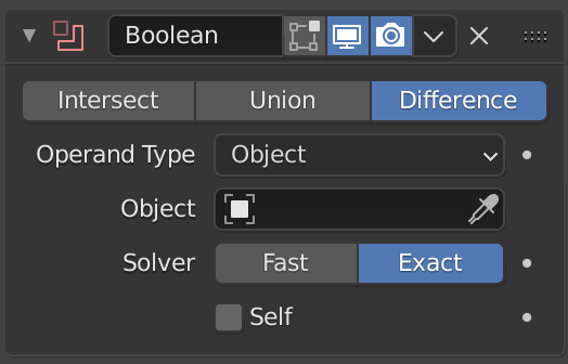
The "Boolean" modifier applies to an object and requests another reference object, the latter 2 will have to react to each other according to the 3 options proposed, intersect allowing only the places of intersection between the 2 objects to be kept, union allowing to merge the 2 objects and difference allowing to remove the places of intersection between the 2 objects.
Via the ALT+Z command, it is possible to see through objects, this can be useful for seeing vertices inside objects, or difficult to see.
There are several working modes, some for manipulating objects such as "modeling" (standard modeling system) or "sculpting" (modeling system used to sculpt shapes). Other working modes are used for multiple situations: creating textures (shading), painting textures (texture painting), managing animations (animation) etc. For this project we only used: layout, uv editing and shading.
Snap mode acts like a magnet, once the option is activated, it is possible to move objects or parts of objects so that they can stick to shapes, other objects or others. surfaces.
When this option is activated, it is possible to modify parts of objects so that all the elements near the area generated with a size adjustable via the wheel follow the modification made.
The spin tool allows a rotation of an object around the mark by creating a number of predefined iterations of this same object.
The basis of this work is the creation of 3D objects. For this we use the layout working mode which has the same usefulness as the modeling working mode.
For the firearm, we needed a weapon that was primarily symmetrical, for this we used a modifier called "Mirror", the latter allows you to achieve symmetry on a specific axis. Afterwards, nothing is complicated, all you have to do is start with a cube base cut in two so that the other side is the mirror and then extend it and change the shape so that you can create the firearm.
For the cannon I just need to add a cylinder that I will have to attach to the rest of the weapon. For this we had a first approach which is to select the 2 models and perform the Ctrl+J command. However, this option poorly merges the 2 objects, this merger does not delete the elements which will nest inside one of the objects, which creates additional vertices that are of no use and this is not optimized to then be imported into the game.
For this we will use "Boolean" modifier on the firearm with the sight as target object, the latter has 3 options, intersect, union and difference. We will use the union option which will merge the 2 chosen shapes by changing their arrangement so as not to have excess vertices inside the object.
For the viewfinder, we simply created the desired shape but we had to ensure that this new object merged with the weapon object thanks to the "Boolean" modifier in the union option.
The pillar is undoubtedly the most complex model in the game because it is made up of a large number of merged elements, the difficulty was mainly to make it beautiful but above all not very demanding for the game.
The structure is very simple. In fact the latter is just a cube flattened then extruded from bottom to top with variations in width. However, elements of the pillar happen to be curved, this effect was possible thanks to the “subdivision surface” modifier, however the pillar ended up with many more vertices than expected. Being a simple shape, it was easy to adjust it with the auto merge option allowing me to remove unnecessary and overplaced vertices.
The shape of the diamond base was not complex, using the boolean modifier was enough to create it easily. The complexity lay in attaching it to the pillar. In fact, moving it by hand would have generated unprofessional work. I therefore had to change the origin of my object to the center of the face that I wanted to stick to the pillar and then use the snap tool which allowed me to hang my base on the pillar at the height of my choice and above all with the right angle. Subsequently I had to use the spin tool to create a 90° iteration around the pillar to create a shape on the side and then use the Miror modifier so as to place it on the 4 faces of the pillar.
The skull was by far the most complex shape. For this I had to create a default model which is that of a monkey's head (blender can be… peculiar). This same head once cut in 2 with the mouth and ears removed as well as with the modified mirror, was a solid base to create the skull. Afterwards, I just had to use the Proportional editing functionality to shape it as I pleased. Once the shapes are made from the top of the skull, I create teeth with a sphere as a base and I merge the elements. However during the process, I used many Surface Subdivision modifiers which created an object with too many vertices. The object being far too complex, the merge together option was not possible. So I used the decimate modifier which is the opposite of Subdivision Surface, will reduce the number of vertices to the minimum possible while keeping the desired shape as much as possible, the vertices are however placed in a somewhat random manner but this does not pose a problem. real problem given that this object will remain a decorative element and will not undergo animations.
The flame holder has the unique shape of the arrow, the latter is simply made in 2D then extruded in 3D. This technique is very regularly used in the creation of 3D models.
The door at the back of the game is not at all complex far from it, it is just an object to which we would have applied the mirror modifier.
Since the models are created we need to assign a texture to it, for this 2 options are available to us: take textures already available on the web, the latter are free of rights and free but it is difficult transform it to our will, or create our own procedural textures, this method is complex and requires learning on blender texture nodes. We will take the latter option.
For the game we use 3 textures: bricks and 2 stone textures, one smooth (stone) and one grainy (sandstone).
In this part, we will explain to you how the shading principle works in blender.
Before creating a texture, we need to do the shading which will be in BSDF format. The latter have specific values such as its color, its metalness and its roughness as well as its normal.
Metalness, being between 0 and 1, allows us to know if our shading is closer to a dull color resembling plastic (close to 0) or a metallic color (close to 1).
Roughness, being between 0 and 1, allows us to know if our shading reflects light, the latter depends on our metalness, the closer the latter is to 1, the more the changes in roughness will be visible. The closer the roughness is to 1, the more it will reflect light.
Normal influence the way light interacts with surfaces to create light and shadow effects. A good adjustment of normals is essential to obtain a realistic rendering, because it directly affects the shading and the perception of shapes in the 3D scene.
To do the shading, I had to understand the nodes to use.
The Color Ramp in Blender allows you to create a color gradient between two or more points, which can be used to control and customize the color transition on a material. It is often used to adjust texture effects, such as shadows or diffusion, based on values such as position, light, or other parameters.

Bump in Blender simulates surface details, like bumps or dips, by changing the way light interacts with a surface without changing its actual shape. This allows you to create more complex and realistic textures without increasing the number of polygons in an object. It is possible to increase the power of this effect by increasing the strength.

The Musgrave Texture in Blender is a type of procedural texture that generates complex and organic patterns, such as terrain, clouds or natural noises. It allows you to create varied and detailed surface effects, by adjusting parameters such as scale, contrast, and noise type.

The Noise Texture in Blender is a procedural texture that creates a random pattern of dots, often used to add irregularities or detail to a material. It is used to generate effects such as grain, roughness or subtle variations in surfaces to make objects more realistic.

Voronoi Texture in Blender generates a pattern of cells or "spots", based on randomly distributed dots, reminiscent of natural patterns like marble veins or reptile skin. It is used to create organic and varied textures, with adjustable parameters to control the size and appearance of cells.

The Texture Coordinate in Blender provides information about the position of textures on an object, determining how they are applied and oriented. It allows you to choose different types of coordinates, such as UV, object, or world, to better control the appearance and alignment of textures on 3D surfaces.

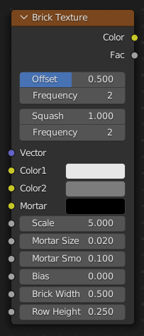
The Brick Texture node in Blender creates a repeating brick pattern, with adjustable parameters for size, color, and joint pattern. It is used to simulate brick or paver surfaces, allowing you to customize the appearance of architectural materials in 3D scenes.
Here we are with complete models but our work does not end there. By importing the 3D models to unreal in a .FBX format, they can end up with inverted faces, that is to say that the latter are invisible outside the object but visible inside because yes the texture are only displayed on one side of each face of the object. To do this we just need to recalculate the "normals" which allow us to put all the textures back outside.
But despite this another problem arises before us, the latter is that our shading cannot be imported into unreal because the latter does not interpret the color ramp. We will need to "bake" our textures, which means that we will create a .png format of the color, the roughness, as well as the normals to create a texture.
For this we need to create the UVs of our objects, which means that we will have to spread out our object like a cube that we would spread out in its pattern. For this we use a “Smart Uv Project” which will take care of this for us. Then we will "bake" the colors, the roughness, as well as the normals on different .pngs to then be able to import them into unreal.
